So I plugged the my Uzebox into the Pacman CRT directly with RGB and Sync. The picture is stable, but it is very dim. I have the brightness set up to where it should be for the Pacman motherboard. Is there a certain spot on the R2R ladder that I should be taking the signal from?
What is the expected voltage & input inpedance for these monitors? Are you taking the signals before or after the 100nf capacitors?
As some of you may remember, much of the time I'm designing JAMMA arcade game boards for a living, so feel free to ask me questions-- I probably know the answer off the top of my head.
Arcade games use video signal levels left-over from when monitors were driven directly from TTL outputs. So essentially "full brightness" is in the neighborhood of ~3-3.5V and black is generally 0.4V or under (lower is better).
What you want to do on the Uzebox is remove the pulldown resistors on the video DAC outputs (the 75 ohm resistors on the schematic) -- that should give you more or less perfect output levels for a standard resolution arcade game monitor.
(It works fine, BTW. All my original testing was on my JAMMA test rig here since that's usually what I'm dealing with.)
As some of you may remember, much of the time I'm designing JAMMA arcade game boards for a living, so feel free to ask me questions-- I probably know the answer off the top of my head.
Right, I forgot about that
Arcade games use video signal levels left-over from when monitors were driven directly from TTL outputs. So essentially "full brightness" is in the neighborhood of ~3-3.5V and black is generally 0.4V or under (lower is better).
What you want to do on the Uzebox is remove the pulldown resistors on the video DAC outputs (the 75 ohm resistors on the schematic) -- that should give you more or less perfect output levels for a standard resolution arcade game monitor.
Your right, I was doing some research and found that most monitors used TTL signals. I'll give that shot and see what happens. Also, the monitor is connected before the capacitors on the DAC.
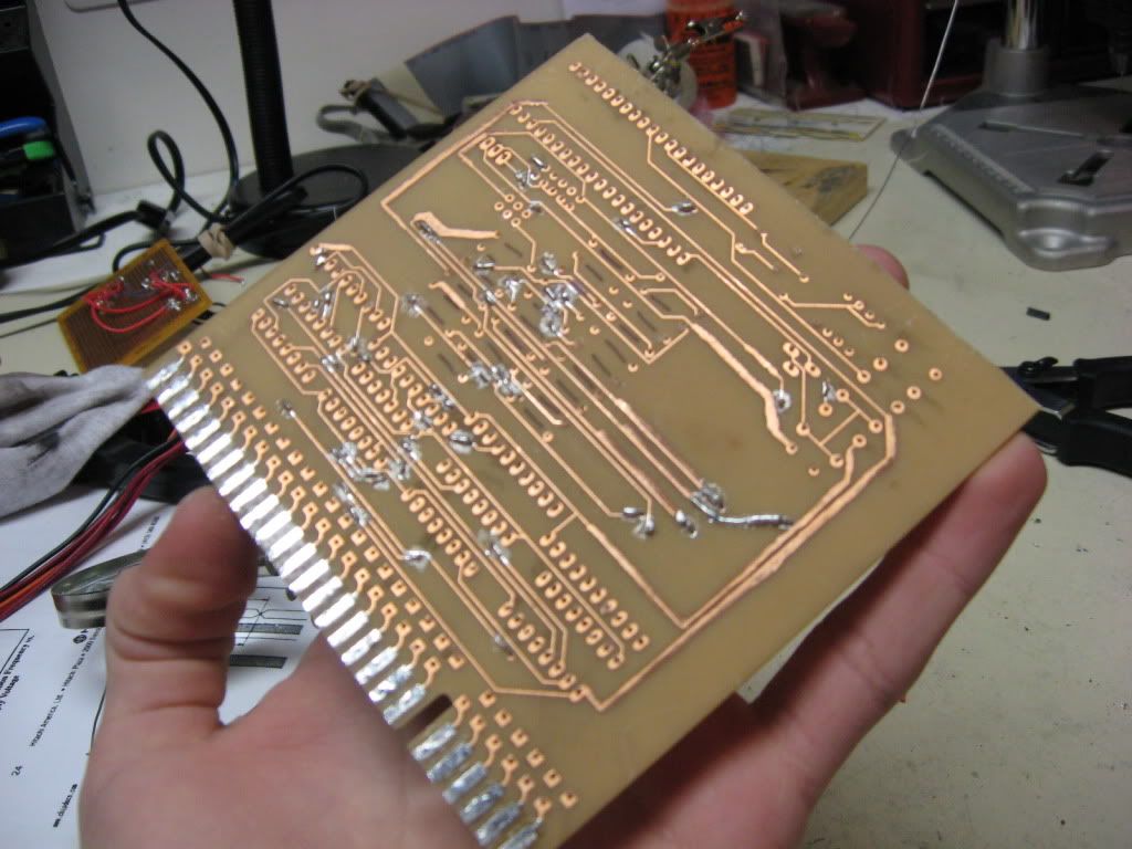
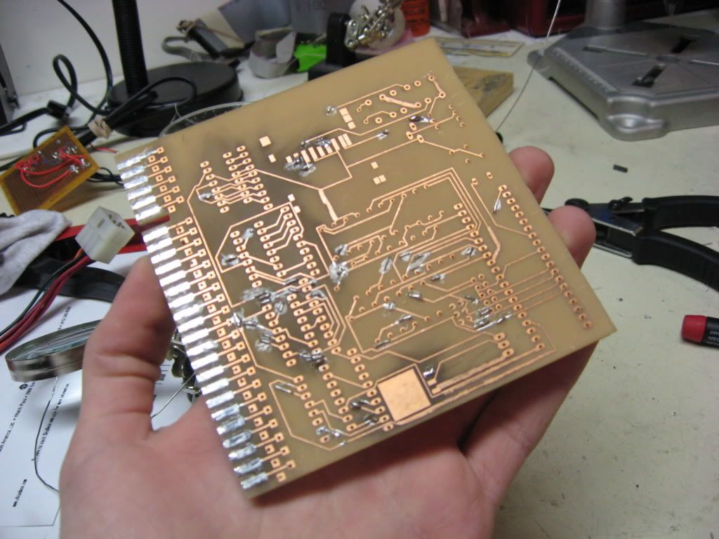
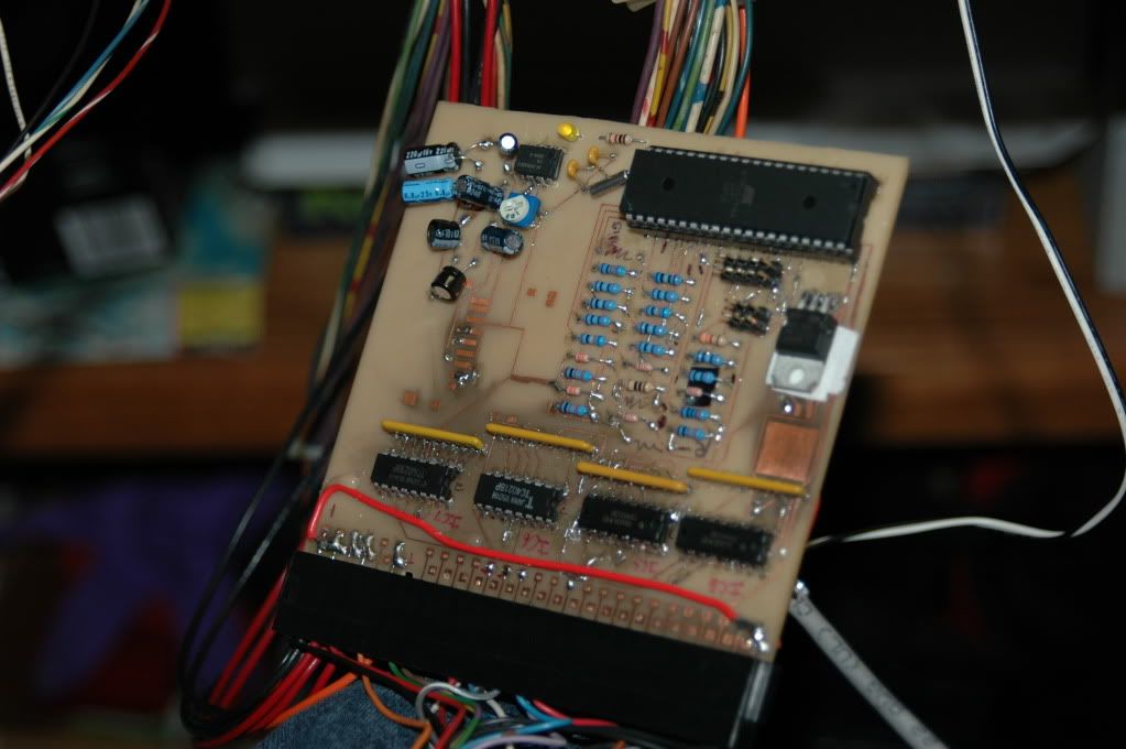
One more thing, I completed etching the Prototype JAMMA board! Here are some pics:
Ya, Clay to the rescue! Very nice board btw! Jeez I need to find a cabinet...or I'll build one! If I'm looking for parts like buttons & joysticks, any good place I could go to order from?
Cool, thanks for the links! I didn't even know Sparkfun carried this kind of stuff.
Oh, heyyyy... Don't buy anything just yet. Let me dig some stuff out of storage.
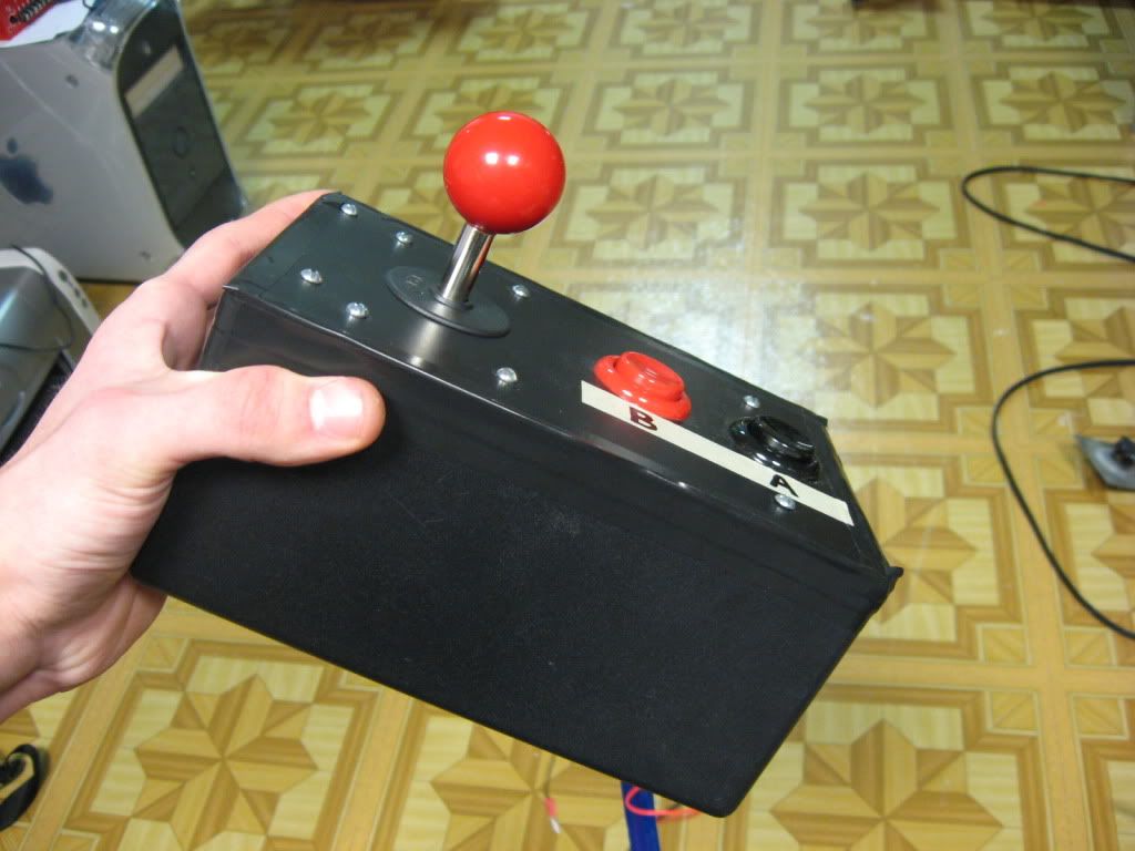
IIRC, I have a bunch of (new, unused) control panels off of the Midway Arcade machines from a few years back. They're not quite 100% arcade quality, but they're dual joystick with six buttons per side (no, I don't know why!) plus P1 and P2 Start-- all in a self-contained unit plastic 'box' type thing.
Here's a pic of sorts-- it's just the control panel portion of this image:
DaveyPocket wrote:
Your right, I was doing some research and found that most monitors used TTL signals. I'll give that shot and see what happens. Also, the monitor is connected before the capacitors on the DAC.
Yes-- DC coupled video. Actually, if you're running from a 5V AVR, you might change the 75 ohm pulldowns to just something like 1K. I had 3.3V supplies stuck in my head, so removing the pulldowns entirely from a 5V AVR might be a little too hot for some monitors.
One more thing, I completed etching the Prototype JAMMA board! Here are some pics:
Looks good! Did you use rub-off decals or one of the toner-transfer methods?
Looks good! Did you use rub-off decals or one of the toner-transfer methods?
I used a toner transfer method. I printed the designs on two sheets of photo-gloss paper, then transferred the designs with a clothes iron. I tried using a laminater but the motors weren't strong enough and it jammed every time.
Just a quick question, which cabinet should this device be dedicated to? (I was thinking maybe a Pacman style cabinet or Nintendo cabinet, or should I find one with lots of buttons on it?) The only cabinets I have right now are Zaxxon, Pacman, and Space Invaders Deluxe.
I am almost done building the device, I just need to get some more parts (I only had 2 4021's for the controls).
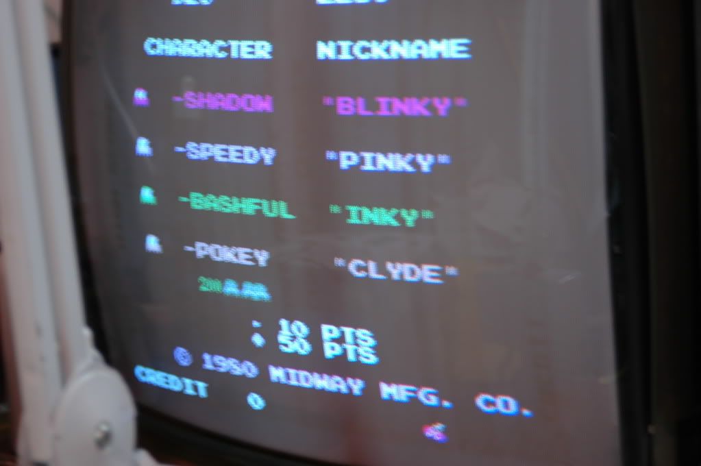
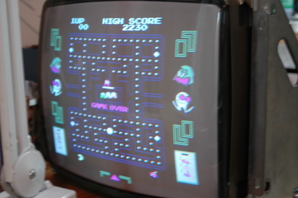
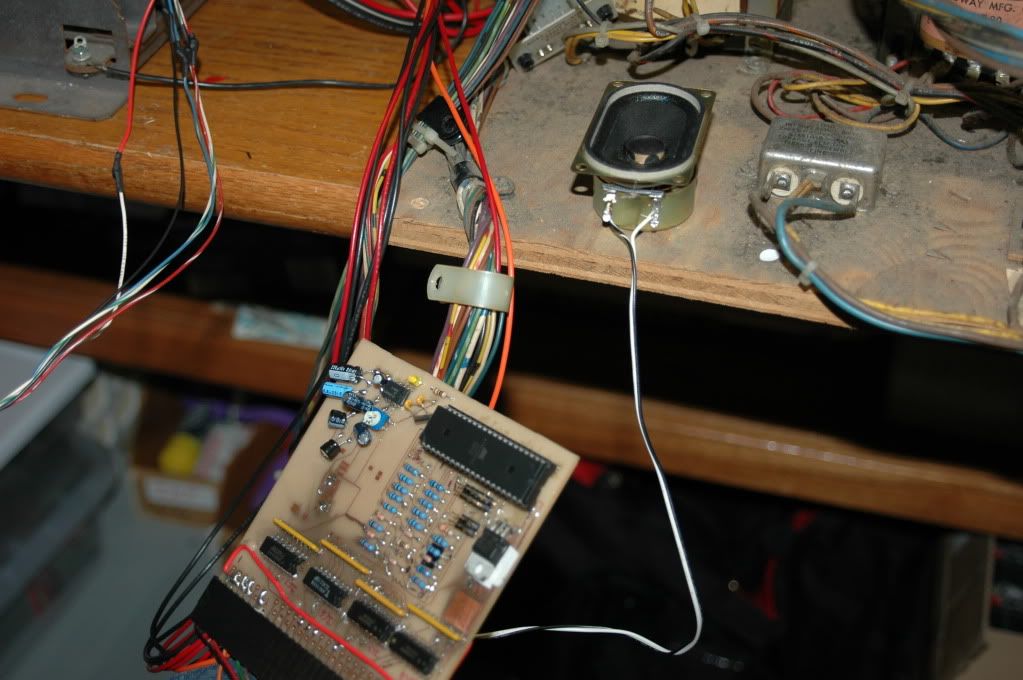
So I finally got my parts from digikey. I had finished it last week but hadn't had time to photograph it. So here are some pictures:
As you can tell from the pictures, the colors are not correct. I'm not exactly sure why this is happening, though I do believe something in the DAC is either shorting or not connecting. Also, I haven't been able to get the controls working (I believe I wired the 4021's completely wrong). I might need to revise my schematic
For some reason, the audio amplifier has been putting out interference. I'm not sure if it's because the board is exposed to a CRT and power supply, or if the switching power supply is putting noise on the 12 volt line.