Yep, it should. It's just standard 0.1" pin spacing with the rows 0.6" apart. (same as a dip socket)CompMan wrote:Will it fit in a standard breadboard?
-Clay
Yep, it should. It's just standard 0.1" pin spacing with the rows 0.6" apart. (same as a dip socket)CompMan wrote:Will it fit in a standard breadboard?
Agreed-- I don't think that'll be much of a problem. If any other manufacturer's are making/start making microSD cards it would actually be more effort for them to strip out the SPI support from their NAND controller than to just leave it in... So I suspect they will likely all have SPI support by default.uze6666 wrote:About the Micro SD, a few mentioned the potential lack of SPI mode. I would not be concerned since two of the big makers supports it: Sandisk and Kingston (See Clay's last picture).
Thinking about it, if used standalone, we need to wire it for power anyways. A few more wires for the ISP wouldn't bother much IMHO. Since the goal was to put all the "complex stuff" on the stamp, I'd say that there's much more value in having a sound filter/op-amp there than the ISP socket if there's no more room.For now I'm leaving the ISP header on there, but maybe we'll drop it for the production spin? (I could put down an optional audio output filter/volume control there instead maybe...)
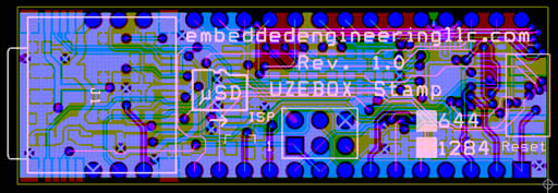
On the contrary, it's pretty cool to see it there. If you can just put a small "tm" after it (I reserved the TM), consider this an "official written permission"If you don't want me to put UZEBOX on it, just let me know
I talked myself in and out of it about three times.uze6666 wrote:Thinking about it, if used standalone, we need to wire it for power anyways. A few more wires for the ISP wouldn't bother much IMHO. Since the goal was to put all the "complex stuff" on the stamp, I'd say that there's much more value in having a sound filter/op-amp there than the ISP socket if there's no more room.
Same here... Open for comments.I'd be curious to hear what others have to say about that. But I agree it should be removed for prod.
Cool, I'll see what I can do. I can't promise the TM will show up very well though! (the picture is deceiving... the text is only 10mil wide lines and the smallest I can do is 6 mil, so it'll be pretty small as a superscript!)On the contrary, it's pretty cool to see it there. If you can just put a small "tm" after it (I reserved the TM), consider this an "official written permission".
Thanks-- but thank you for coming up with something worthy of doing some custom hardware for!Best regards and congratulations for this amazing work.
Yep, I was eager to try a few. An "kitchen sink" version with MIDI/serial/joysticks/expansion headers/etc., then maybe a "game" one (joysticks, A/V only), then maybe a 'micro' one. (like buy one of those "tv game" joypads and make a compatible PCB for it that includes the stamp onboard.)ps: Are you planning do produce a baseboard around the same time? I guess after we settled that joystick connector issue...
What I did was use PD6 for the 'card select'. There was really only three reasons for that-- 1) a commercial SD/CF FAT library I bought for another project used it, and 2) I went ahead and called the rest of PD3-PD5 "SPI_CSx" for a total of four. 3) It just so happened that PortD routed on the PCB much better because of its proximity to the ISP header which I had to run the SPI signals out to anyway... The resulting pinout is a little "different". It's a hardware engineer pinout.uze6666 wrote:Btw, did you use a pin for the Micro SD slave select? I'm trying to allocate pin and right now, the most obvious would be PB4 (SPI SS). Also I'm wondering: if putting a regular SD on the baseboard, why not make them mutually exclusive? That would take up only one SS pin for the SD function. What's the risk of both were plugged simultaneously? Is there some sort of line contention protection on the SD cards?
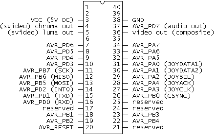
The pins on the 'DIP' module marked as reserved are loaded (there's a pin there), but they don't go anywhere. I didn't have any other pins on the AVR that *had* to go out and I didn't really want to eat up all the pins just because they're there without thinking about it more...uze6666 wrote:Fair enough for PD6! Great to see that universal joystick interface laid down. I will just have to upgrade the API to support the new kinds. The pins you marked as reserved in your schematic are currently NC?
Ahhh, gotcha. I immediately think of all the 'official' patent/trademark stuff that the corporate types here immediately do.Oh and I didn't register the trademark since its not required (common law trademark).
