Page 16 of 21

Re: The quest to a portable Uzebox - update!

Posted: Sat Nov 17, 2018 12:13 am
by uze6666
Oh yes, of course, the schematic...that would help! :) Here's the latest schematic, PCB & BOM.

I'm starting to build the latest rev, so hopefully moving the esp12 away will do the job. *praying*

Edit: Important, I just realized the BOM is not up to date, some parts are wrong so don't use right away, I will correct it.

Re: The quest to a portable Uzebox - update!

Posted: Sun Nov 18, 2018 4:24 am
by CunningFellow
I'm not sure of the function of C14 in that circuit,

I think an active stage between the AVR and the LM386 could help.

Re: The quest to a portable Uzebox - update!

Posted: Wed Dec 12, 2018 10:03 am
by Kilo
Why are you using this circuit for the LM386?
Does it really works fine?

Some other idea for the portable uzebox would be to make a uzebox switch like the Nintendo one.
Building a dockingstation for the tv where you can put your portable uzebox in it in order to charge it AND play the games on tv :D

Re: The quest to a portable Uzebox - update!

Posted: Thu Dec 13, 2018 7:31 pm
by D3thAdd3r
I like the switch idea. It might be hard to develop a case/socket/dock that works well mechanically, but it is probably possible and could be an interesting modification.

Re: The quest to a portable Uzebox - update!

Posted: Mon Dec 17, 2018 1:54 am
by ry755
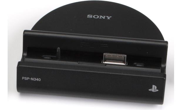
It could be something simple like the PSP Go dock:

ImageImage

Re: The quest to a portable Uzebox - update!

Posted: Thu Jan 24, 2019 12:41 am
by uze6666
Update time! I'ts been a long time, been quite busy with those other things in life :) but was regularly working on it. So happy new year to all!
uzebox_portable_1_4.jpg
uzebox_portable_1_4.jpg (221.12 KiB) Viewed 7188 times
Well, rev 1.3 didn't work so well. The idea of plugging the 8266 directly on the battery kinda work when the battery was getting low (under 3.5V) but I fried the module when the battery was fully charged at 3.7V+. :cry: :roll: But at least when it worked, this totally solved the clicking problems. It really seems the powerboost module could not fully handle those current pulses required when transmitting.

Anyhow, went back to the drawing board and put the regulator directly on the battery instead of piggybacking on the powerboost. Since a dead battery is about 3V and the ESP8266is stabled at ~3.1V (but not fully at 3.0V after testing), I changed the 3.3V regulator for a 3.1V one. ESP8266 and SD works fine and no more clicks on the audio. :P

Also updated some little things here and there (like replacing that expensive switch) and added two optional tactile switches to help flash the 8266. Pretty happy with it and after all the expenses of the previous revs, I'll call this one done. I'll publish averything so if anyone wants to improve, it's all yours.
I'm not sure of the function of C14 in that circuit,
When I was trying to improve the noise issue I saw on some site a guy that said it could improve noise pickup immunity or something like that. So sure it really helps but I decided to put the footprint anyway just in case. It much prefer to have empty/optional footprints than have to order another batch of PCBs if it ended up being required. I'll do all my tests and if really not required, I'll remove it from the design.
Why are you using this circuit for the LM386?
Does it really works fine?
I compiled all the design notes and examples I could find and it gave that. Now, yes it works fine, though the noise level is a bit noticeable at mid-full volume, probably because of the noise on the power line due to the powerboost and also the remaining ripple out of the PWM DAC. BTW, speaking of the powerboost noise, it conveniently happens that the LCD module board actually filters out a LOT of it for some reasons!
Building a dockingstation for the tv where you can put your portable uzebox in it in order to charge it AND play the games on tv
It's a neat idea. Initially I wanted to have a simple A/V jack to enable it to be plugged in a TV directly. But I decided against it. First, I was running out of space and then, I would have to cut power to the LCD PCB to save power. But then the noise filtering mentioned above would also go away and result in lots of noise in the speaker. A fully docking approach would be nice but at some point, just like in software deveopment, you have to control scope creep if you want to deliver anything! :lol:

Now to printing the updated enclosure.

Update: btw, on the pic, the screen shows ASCII Starwars streaming on WIFI from the Telehack telenet site. The whole thing runs at 115200 bauds without skipping a single byte. :geek:

Re: The quest to a portable Uzebox - update!

Posted: Thu Jan 24, 2019 5:12 pm
by nicksen782
Could you just leave the LCD on but reduce the backlight? You would need some sort of A/V splitter for TV out. It IS a pretty cool idea. I dunno about a dock since that would require some design changes. However, would it be hard to add an A/V out pin that you could just plug into the portable and a TV and use the portable as the controller. Player 2 is another story but not super-important considering that the tv out is a matter of convenience.

Feature-creep is tough. I get it.

Re: The quest to a portable Uzebox - update!

Posted: Thu Jan 24, 2019 7:49 pm
by Jubatian
Wow, that ASCII StarWars is still circulating around! :D

Great job there, and it looks good on the LCD despite the too low resolution of the panel for the 80 characters wide terminal! I would say, let's have a solid little portable, A/V out could be nice, but if it's too complicated, just drop it. There is the Uzebox DTV for that. This is already a quite delicate project, I can imagine, with all those different voltages.

Re: The quest to a portable Uzebox - update!

Posted: Thu Jan 24, 2019 8:16 pm
by L4rry
Yes!

I'd lie if say I didn't longingly refresh this topic daily for this update. My body and 3D printer are prepared. Great job and thanks for all the effort. Especially since I know you have a family and plenty on your hands otherwise.

I say release the CAD, BOM and STL and let the community take it from there. Once people actually play around with it, it would inform any future iterations better. The suggested changes are great, but the round trip and cost for printing PCBs are coming to a point of diminishing returns I'd imagine.

I am so excited for this :mrgreen:

Re: The quest to a portable Uzebox - update!

Posted: Thu Jan 24, 2019 8:18 pm
by L4rry
Oh and ASCII Star Wars?? My geek mind just got blown. Did not even know that was a thing!