I got two cheap db9 joypads and opened one up to find 5 wires and a chip under a glob of epoxy. Not knowing what the chip is, is there any way I can decode what this joypad is doing? It's Sega-style with 6 buttons, start, select, and directional pad. First, how do I know which wire is vcc, ground, data, clock, and latch? Once I figure that out, how can I decode the data? I am a newbie at AVR development, so forgive me if this is basic. Do I need an oscilloscope, or can I hack together something on the AVR to read the data stream and light up some leds for feedback?
I found this to be helpful:
http://seb.riot.org/nescontr/
Hacking a joypad
Re: Hacking a joypad
If it's a genesis style pad, I'd start with a genesis pinout:
http://pinouts.ru/Game/genesiscontroller_pinout.shtml
You can try to look at the PCB layout and see if two of the traces are larger than the rest-- those will often be power. Similarly, most switches will close to ground, so if one side of all the buttons are connected together that's probably your ground.
If there's a power bypass capacitor (doubtful), that can be handy to identify power as well.
You can certainly use the AVR to just rattle the lines and look for appropriate responses. I would suggest putting something like ~1K resistors in series with the signals while you're experiment just so that you can't source or sink too much current if you get something backwards...
-Clay
Re: Hacking a joypad
Thanks, Clay. I've read almost all your posts here and you have been incredibly helpful to my understanding of how this stuff works.
The joypads seem to be only Genesis-style on the outside. The inside only has 5 wires and the pinouts are not the same. I assumed the wires were ground, power, clock, latch, and data. There is a trace that connects all but the top row of buttons. I guess this is ground. All the other wires go directly into the chip. There's no capacitor or anything else on the board.
WhenIlearn some more assembler I might ask some questions on the software board to find out how the Video Engine Core is reading the data lines and sending the clock and latch pulses.
Re: Hacking a joypad
looking at the description it sounds like its more straight-up multiplexed. dunno what it looks like inside but it might be easier to just rip out the 74'152 (?) and replace it with a 4021 http://pinouts.ru/Game/snescontroller_pinout.shtml
Re: Hacking a joypad
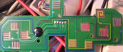
Does the PCB look like this?
http://picasaweb.google.com/lh/photo/LX ... IaZN4blLHA
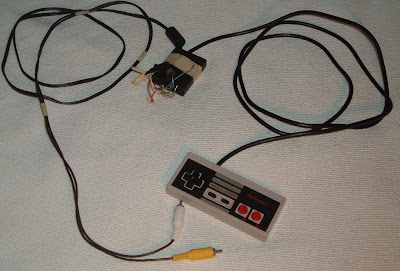
I got this from a 6-button (+ start) Genesis look-alike from the "super joy 3" pack http://en.wikipedia.org/wiki/Power_Player_Super_Joy_III. It should be nintendo compatible, I am sorry but I don't have any pinouts or more info, the controller is currently inside a real NES with the nintendo-on-a-chip:
It looks like I have ground traced, but I am not sure which is power and clock/latch/data. (and this assumes the buttons pull low, which isn't a given.)
http://picasaweb.google.com/lh/photo/LX ... IaZN4blLHA
I got this from a 6-button (+ start) Genesis look-alike from the "super joy 3" pack http://en.wikipedia.org/wiki/Power_Player_Super_Joy_III. It should be nintendo compatible, I am sorry but I don't have any pinouts or more info, the controller is currently inside a real NES with the nintendo-on-a-chip:
It looks like I have ground traced, but I am not sure which is power and clock/latch/data. (and this assumes the buttons pull low, which isn't a given.)
Re: Hacking a joypad
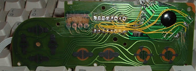
The PCB looks very similar to that, only the layout is a little different. Ladyada, you see the big black blob? That's the chip, so I don't think it will be possible to remove it without damaging the cheap paper board. You could be right about the multiplexer, because when I hooked it up to some LEDs I got rapidly flashing light of varying intensity. The buttons on the right made the lights brighter (flashing faster) and the left side was dimmer (the flashing was visibly slow). However, on the back of Nubie's board there is a label "8582B" which seems to be a parallel to serial shift register like the 4021.
Re: Hacking a joypad
I am pretty sure with a dremel or a knife you could pop that off, or just re-wire it like I did:rlaw wrote:The PCB looks very similar to that, only the layout is a little different. Ladyada, you see the big black blob? That's the chip, so I don't think it will be possible to remove it without damaging the cheap paper board. . .
http://picasaweb.google.com/lh/photo/D0 ... ffuEGINJTA